Turn-Key Vibratory Feeder With Bad Part Reject And Integrated Isolation Mechanism
Jump to: System Specifications || Quote Request Form ||Download Flier
This vibratory feeder with custom conveyor belt tracking was designed to feed 2 styles of plastic parts into a consumer appliance assembly operation. The application required 4 lines of parts (2 lines of a left-hand version and 2 lines of a right-hand version), with each line alternating between the left-hand and right-hand part version. Each bowl feeder had to allow for the possibility of the wrong part being in the system, and an isolation mechanism was required so that 2 parts could be picked up from each line simultaneously.
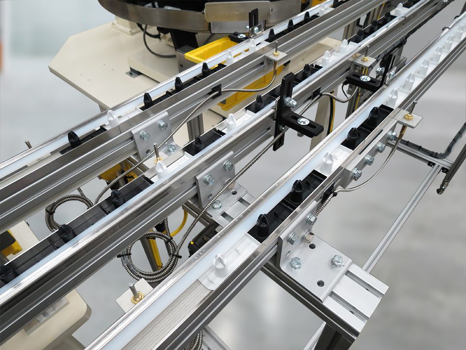
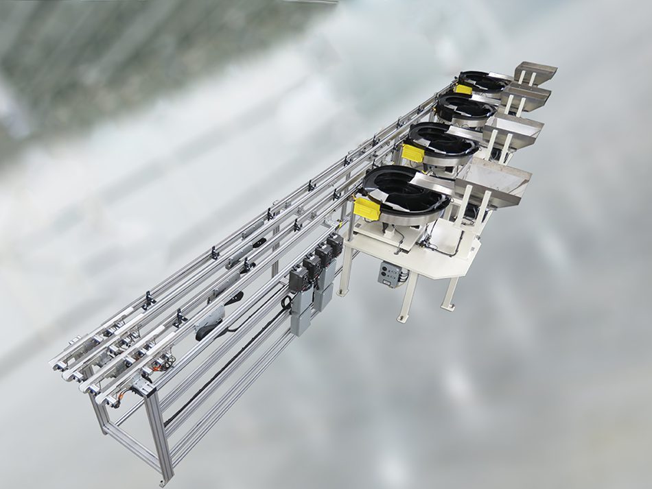
We designed a system that included 4 vibratory feeder bowls, with 2 bowls feeding the left-hand part, and 2 bowls feeding the right-hand part, feeding the oriented parts into 4 integrated belt conveyors with isolation mechanisms at the conveyor outputs.
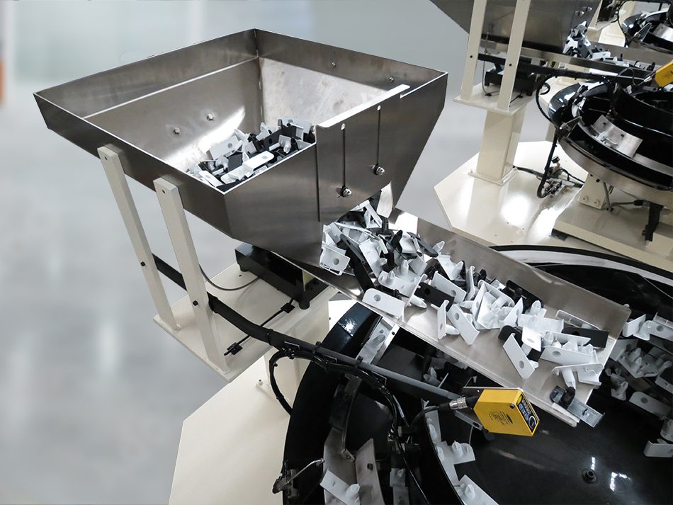
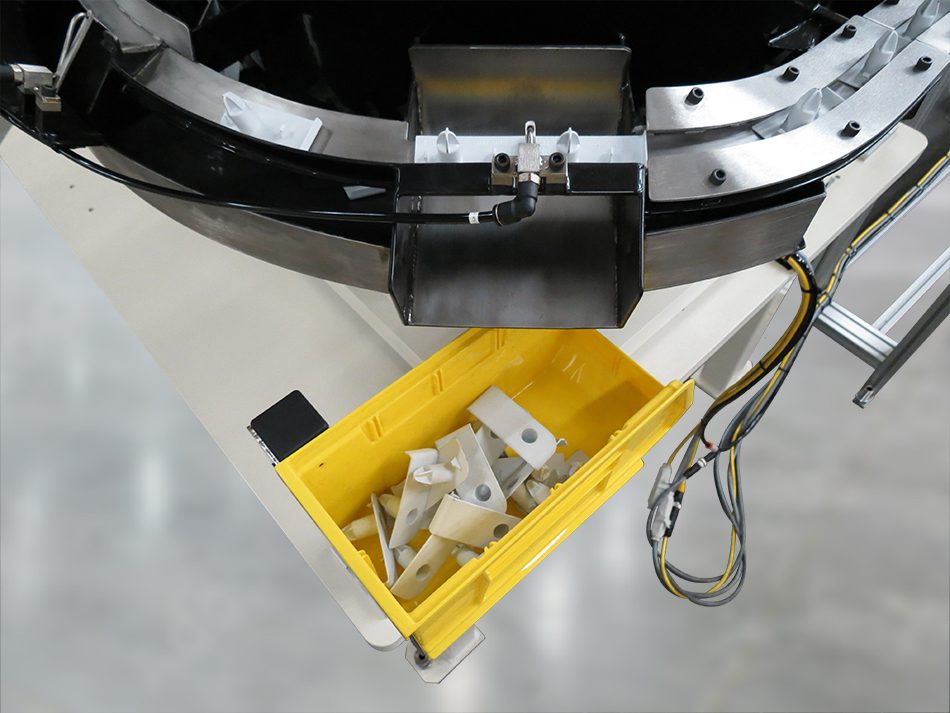
View this short video that demonstrates parts as they leave the bulk supply hoppers and are fed into the four vibratory feeder bowls. The sorting feature of the feeder bowls rejects incorrect parts prior to feeding them into the bank of 4 belt conveyors. The 4-position isolation mechanism allows 2 parts to be placed into the assembly operation and 2 parts to be queued into the pickup position.
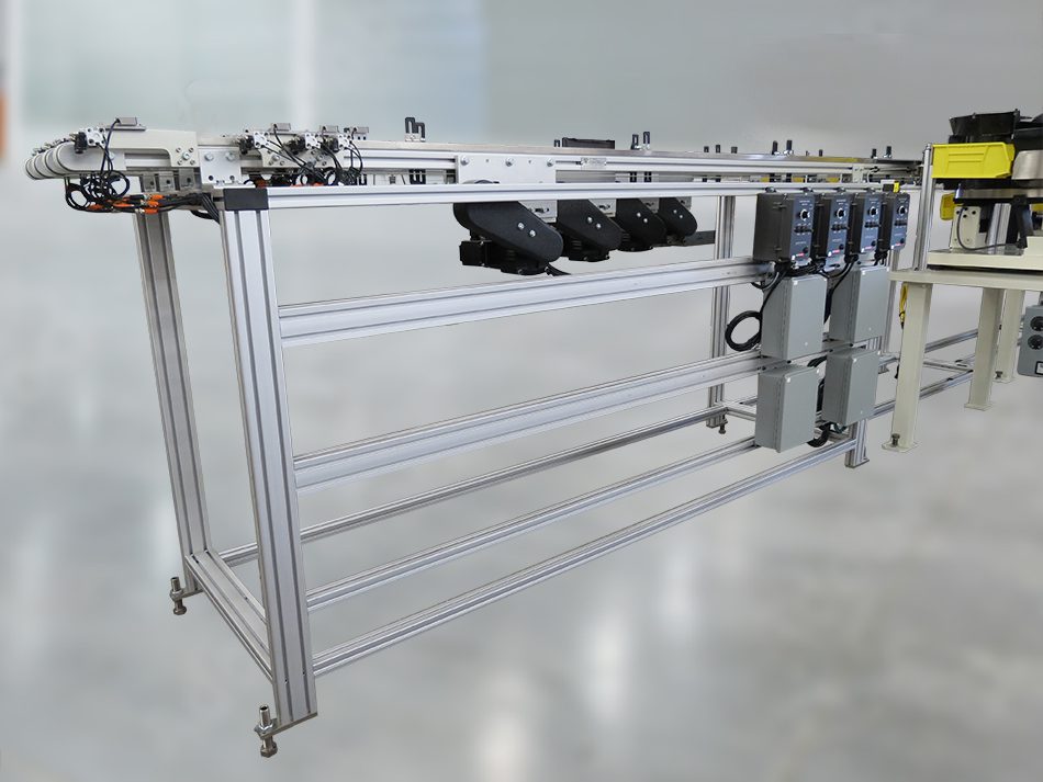
The vibratory bowls fed the oriented parts into a bank of 4 Auto-Kinetics belt conveyors, with center drives, mounted onto a common stand framework. The conveyor motor controllers and junction boxes (that all the sensors that interfaced with the assembly machine’s control system were wired into) were also mounted onto this stand.
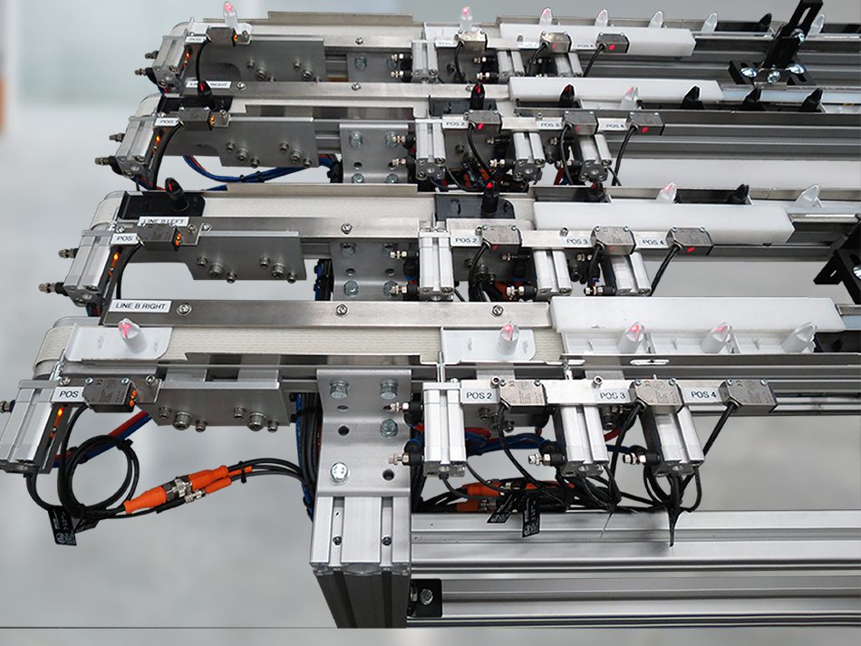
4-position isolation mechanisms were located at the end of each conveyor, providing for 2 parts in position to be placed into the assembly operation, and 2 parts queued to move into the pickup positions. Each escapement cylinder included sensors to detect whether the finger was extended or retracted, and a proximity sensor to detect whether a part was in place.
System specifications
- Feed Rate:10 parts per minute, per line.
- Input voltage: 120V, 60 Hz.
- Vibratory bowls (4):
- 27″ basic diameter.
- Counterclockwise rotation.
- Polyarmor coating.
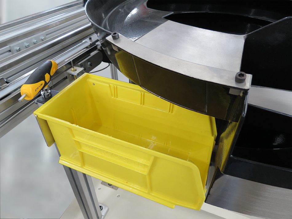
- Purge gates with catch bins for part changeover.
- Reject chutes with catch bins to reject wrong type of parts detected in feeders.
- Belt conveyors (4):
- Auto-Kinetics Model 55 standard duty belt conveyors, 40mm wide.
- Staggered conveyor lengths of 3401mm, 5079mm, 6757mm and 9182mm.
- Center drives with 1/6 HP 230V 3-phase AC inverter duty motors.
- All conveyors mounted to a common floor stand system with 156mm spacing between conveyor centers.
- Bulk supply hoppers (4):
- 3 cu. ft. capacity with table mount.
- Stainless steel bins and trays.
- Purge doors for part changeover.
- Isolation mechanisms (4 sets): 4-position escapement mechanisms on each conveyor, positioning 2 parts for pickup and 2 parts queued to move into pickup positions.
- Controls:
- (4) Performance Feeders PF-2R, 1 for each bowl/hopper set.
- (4) KB Genesis KBAC-24D AC variable speed motor controllers, 120VAC 1-phase input, 230V 3-phase output.
- (4) Junction boxes for sensors that interfaced with the assembly machine’s control system.
- Mounting surfaces (4): 1.25″ thick steel tables with 5 legs for each bowl/hopper set.
- Sensors and valves provided:
- (4) Photoelectric sensors on conveyors, monitoring part level in conveyors. When a conveyor is full, the bowl supplying the conveyor is turned off to prevent parts from backing up into the bowl.
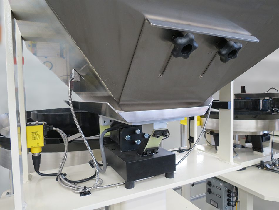
- (4) Proximity sensors on hoppers, monitoring part level in bowls, turning on the hopper supplying the bowl when parts are needed.
- (4) Photoelectric sensors on hopper bins, monitoring bulk part level in hoppers. Wired to junction boxes for interface with the customer’s control system.
- (32) Integrated sensors on escapement mechanisms, detecting when each escapement finger is extended or retracted. Wired to junction boxes for interface with the customer’s control system.
- (16) Proximity position sensors on escapement mechanisms, monitoring where parts are in place at each escapement. Wired to junction boxes for interface with the customer’s control system.
- (4) Solenoid valves with regulators and flow controls for air jets on each of the bowl feeders.
Downloads
Performance Feeders Tri-Fold Brochure
Vibratory Feeder Bi-Fold Brochure
Vibratory Feeder Rack Card

